Multibeam bathymetry is the standard method for high-resolution seabed mapping in marine construction, dredging, pipeline route assessment, and port development. A multibeam echosounder does not measure depth directly. It measures acoustic travel time and arrival angle for a fan of beams, then converts these values to depth using the speed of sound through the water column. Small errors in sound velocity or sensor geometry propagate into bathymetric surfaces and can affect volume calculations, slope stability assessments, and foundation design.
Physical Principles of Multibeam Echosounding
A hull-mounted or pole-mounted transducer array emits a short acoustic pulse across a wide swath perpendicular to the survey line. The receiver array listens for seafloor returns in many narrow beams. For each beam, the system records two-way travel time and beam steering angle. If the speed of sound were constant and known, depth below the transducer would be calculated from the relationship between travel time, angle, and sound speed.
The apparent depth from a single beam is calculated as d = (c × t × cos θ) / 2, where c is the mean sound speed, t is two-way travel time, and θ is the beam angle from vertical. This relationship assumes the acoustic path is straight; in real water columns, refraction bends the path.
Swath width depends on beam opening angle and water depth. Shallow-water multibeam systems commonly operate at frequencies from 200 kHz to 400 kHz, producing narrow beams and dense soundings, while deeper-water systems use lower frequencies such as 30 kHz to 100 kHz to reduce attenuation. The across-track resolution is not uniform; outer beams travel farther and encounter greater refraction and footprint spreading than nadir beams.
Frequency Selection and Swath Coverage
Frequency selection is not only about range. Higher frequencies provide smaller acoustic footprints and better target detection in shallow water, but they also attenuate more quickly. Lower frequencies propagate farther but produce larger beam footprints and lower spatial resolution. For dredging, rock placement, and berth pocket surveys, the project tolerance determines whether a 400 kHz system or a lower-frequency system is appropriate. Geomak selects the echosounder frequency based on water depth, required survey order, seabed type, and the level of feature detection needed for the engineering task.
Why Sound Velocity Profiles Matter
Seawater sound speed is not constant. It depends on temperature, salinity, and hydrostatic pressure. In coastal and estuarine environments, freshwater input, solar heating, tidal mixing, and seasonal thermoclines create vertical sound speed gradients. A cast taken at the start of a day can become invalid within hours, particularly near river mouths or thermal fronts.
When an acoustic ray crosses layers of different sound speed, it bends according to Snell's law. Without a correct sound velocity profile, outer beams are mapped too deep or too shallow, producing the characteristic "smile" or "frown" artifact in bathymetric surfaces. These artifacts are not random noise; they are systematic and can bias volume estimates.
Refraction at a water layer interface follows Snell's law for acoustics: sin θ1 / c1 = sin θ2 / c2, where θ is the ray angle from vertical and c is the sound speed in each layer. A decreasing sound speed with depth bends rays toward the vertical; an increasing sound speed bends rays away from the vertical.
Modern acquisition software applies ray tracing through the measured sound velocity profile to correct each beam. The accuracy of this correction depends on profile density, temporal sampling, and the position of the surface sound velocity sensor.
Sound Speed Models and Profile Structure
The sound speed in seawater can be approximated by empirical equations that use temperature, salinity, and depth. One widely used approximation is the Medwin equation:
c = 1449.2 + 4.6T − 0.055T² + 0.00029T³ + (1.34 − 0.010T)(S − 35) + 0.016D
where T is temperature in degrees Celsius, S is salinity in practical salinity units, and D is depth in meters. This relationship shows that temperature has the strongest influence on sound speed in the upper water column, while pressure becomes more significant at depth. A sound velocity profile is not a single number; it is a vertical series of sound speed values that captures thermoclines, haloclines, and pressure-driven increases.
Sound Velocity Profiling Methods and Sensor Placement
Geomak uses three complementary measurements during multibeam surveys:
- Conductivity-temperature-depth (CTD) or sound velocity profiler casts: Direct vertical profiles of sound speed from the surface to the seabed, or to the maximum survey depth. These profiles define the refraction model.
- Surface sound velocity probe: A dedicated sensor mounted near the multibeam transducer to record the speed of sound at the transducer face. This value is used for beam steering at the array and should update continuously during acquisition.
- Disposable or underway profilers: In areas with rapid water mass changes, repeated casts or towed profilers reduce temporal error.
Sensor placement is a critical operational detail. A surface sound velocity probe installed far from the transducer or in a different water intake can record a value that does not represent the acoustic path. The probe should be as close as possible to the transducer and in free-flowing water, not in a stagnant pocket or near a warm engine discharge.
System Integration: GNSS, Inertial Motion, and Timing
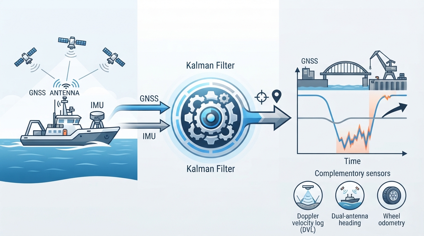
Bathymetric accuracy is not determined by acoustics alone. The multibeam transducer measures ranges and angles relative to the vessel. To place those soundings on a geodetic datum, the survey system must integrate:
- GNSS positioning: Real-time kinematic or post-processed kinematic positioning for vessel reference point coordinates.
- Inertial measurement unit (IMU) or motion reference unit: Heave, pitch, roll, and heading at high update rates.
- Lever arm offsets: Precise three-dimensional vectors between the GNSS antenna, IMU, and transducer. Small angular errors in lever arms produce large positional errors in deeper water or at outer beams.
- Timing synchronization: Position and motion data must be time-stamped consistently with each ping. Latency of even a few milliseconds distorts the swath edge in dynamic conditions.
A practical optimization strategy is to perform a patch test before survey operations. The patch test measures residual latency, roll, pitch, and yaw misalignment by running specific survey lines over a stable seafloor feature. Correcting these values reduces systematic bias across the full swath.
Calibration and Data Quality Control
After refraction correction and motion compensation, Geomak validates the bathymetric surface with independent checks. This includes comparison against single-beam echosounder data along check lines, bar checks in shallow water, or repeated overlapping swaths. The International Hydrographic Organization Special Publication 44 defines survey orders with maximum allowable uncertainty. For example, Order 1a requires total vertical uncertainty at the 95 percent confidence level to be controlled within depth-dependent limits for areas where under-keel clearance is critical.
Operators should monitor swath coverage, nadir gap, outer-beam noise, and bottom detection confidence in real time. Rejected soundings should be logged and reviewed, not simply deleted. A bathymetric surface built from cleaned soundings must preserve seafloor features that affect engineering decisions, such as scour pits, debris, and bedforms.
Optimization Strategies and Common Pitfalls
The following practices improve multibeam bathymetry reliability:
- Good practice: Acquire a new sound velocity profile before each survey block and after significant tide, weather, or water mass changes.
- Good practice: Monitor surface sound speed continuously and compare it with the profile value used for ray tracing.
- Good practice: Run overlapping survey lines so adjacent swaths can be compared for refraction artifacts and positioning errors.
- Good practice: Perform a patch test after transducer installation, vessel dry-docking, or sensor changes.
- Poor practice: Using a single historical sound velocity profile for an entire project, particularly in estuarine or seasonally stratified waters.
- Poor practice: Ignoring surface sound velocity changes near the transducer, which can introduce systematic beam steering errors.
- Poor practice: Surveying with insufficient overlap or without independent check lines, leaving refraction and motion errors undetected.
- Poor practice: Over-cleaning outer beams to remove artifacts instead of correcting the sound velocity profile, which can erase real seabed features.
Application in Marine and Coastal Projects
Reliable multibeam bathymetry supports dredge volume calculations, pipeline route clearance, rock placement, berth pocket monitoring, and pre-construction seabed mapping. In these applications, the bathymetric surface is not only a picture of the seabed; it is an engineering input. Errors of a few decimeters across a large area can change dredge payment volumes or reduce design confidence.
Geomak integrates multibeam bathymetry with sound velocity profiling, GNSS positioning, inertial motion compensation, and independent quality control so that the final surface is traceable, repeatable, and suitable for marine construction decisions. When seabed data must support structural design or contractual quantities, the survey strategy should treat sound velocity as a dynamic environmental parameter, not a one-time setting.

Comments (0)
No comments yet. Be the first to comment!
Leave a Comment